Building 20 Fenchurch Street in Houdini
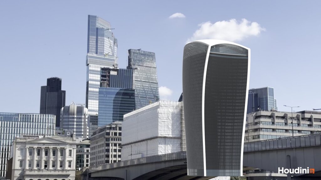
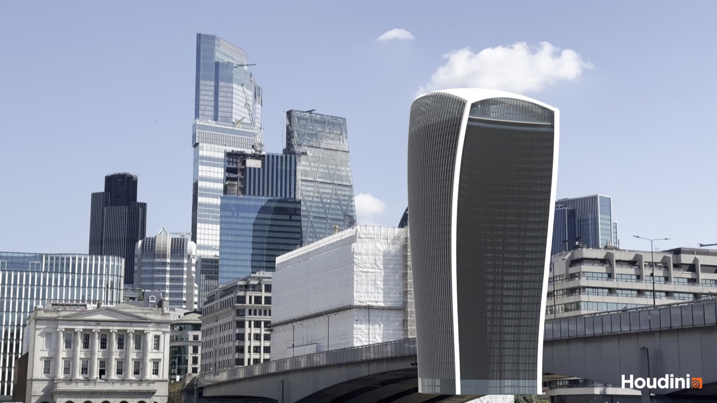
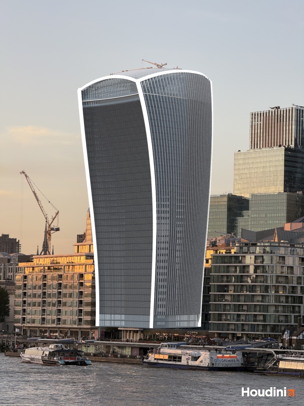
I want to bring down the Walkie-Talkie in London for a fracture shot, and for that I needed a model of the building that an RBD setup can actually use. Looking right isn’t enough. Every part has to be its own closed solid with real thickness, nothing can overlap, and every piece needs a name and some tags so I can pull the floors, glass and fins apart later. So I had Claude Code write a Python generator that builds the whole tower inside Houdini from the planning drawings, and then spent a week of evenings matching it to my plate. This is where it ended up: version 38, rendered in Karma over the first frame of the shot.
Starting from the planning drawings
The City of London planning portal still has the building’s original 2008 application, so the starting point was 19 sheets from it: elevations, sections, a couple of floor plans and the facade details at 1:50. They’re all scans with no text layer, so every number was read off the images, levels from the datum tags on the sections and everything else against the drawing scale. All of it goes into one params file, and each value says which sheet and view it came from and whether it was measured, derived or estimated. There are 248 values in there now, 88 measured, 26 derived and 134 estimated. The estimates are mostly things the drawings don’t show, like the louvre sizes and the slab thickness. The generator code isn’t allowed any numbers of its own, so changing the building means changing the params and rebuilding.


Rules for the geometry
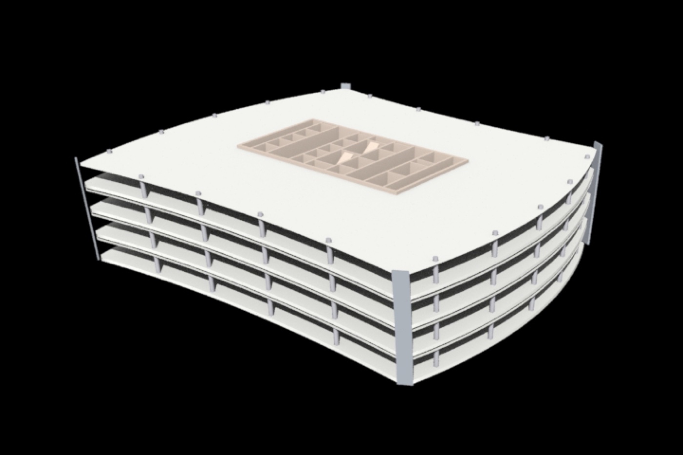
This is the part that matters for fracture. Every piece is a watertight solid with its normals facing out, and it’s built closed from the start with capped extrusions, lofts and boxes, not patched up with booleans afterwards. Pieces next to each other either share a face exactly or leave a 1 mm gap, and nothing overlaps. Each one gets a name like glass_L34_B012 (level 34, bay 12) plus a material, level and bay. After every build a validation pass checks the lot: PolyDoctor for manifold, Measure for the volume of each piece, and an overlap test between every pair of neighbours. If anything fails, that version doesn’t get saved. The final build is 31,299 pieces and takes about two and a half minutes to validate, with zero failures.
Matching the plate
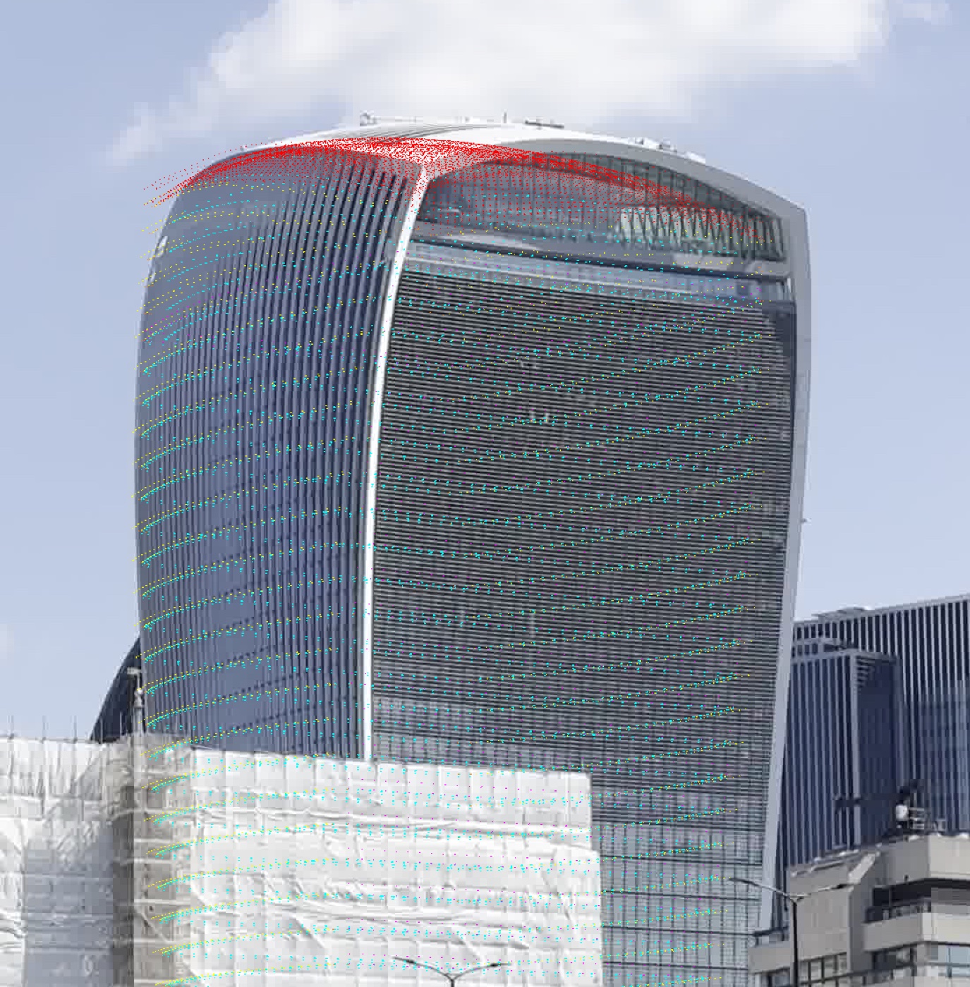
The drawings got the overall shape close, but the crown and the flare of the sides never quite lined up with my plate, a short iPhone clip of the skyline that I stabilised in Nuke. Rather than track it, Claude estimated the camera from a single frame and fitted things to that, like the curve of the white band round the roof. It ended up good enough that I kept it as the shot camera. The plate only shows the front, so for the back of the crown I added a set of sunset photos I took from Tower Bridge and it fitted to those as well. The east half of the model ended up 16 to 19 percent wider than the drawings say, because that’s what the plate shows. Anything that came from photos is marked as estimated in the params, so I know which numbers to revisit if a tracked camera turns up.
The crown
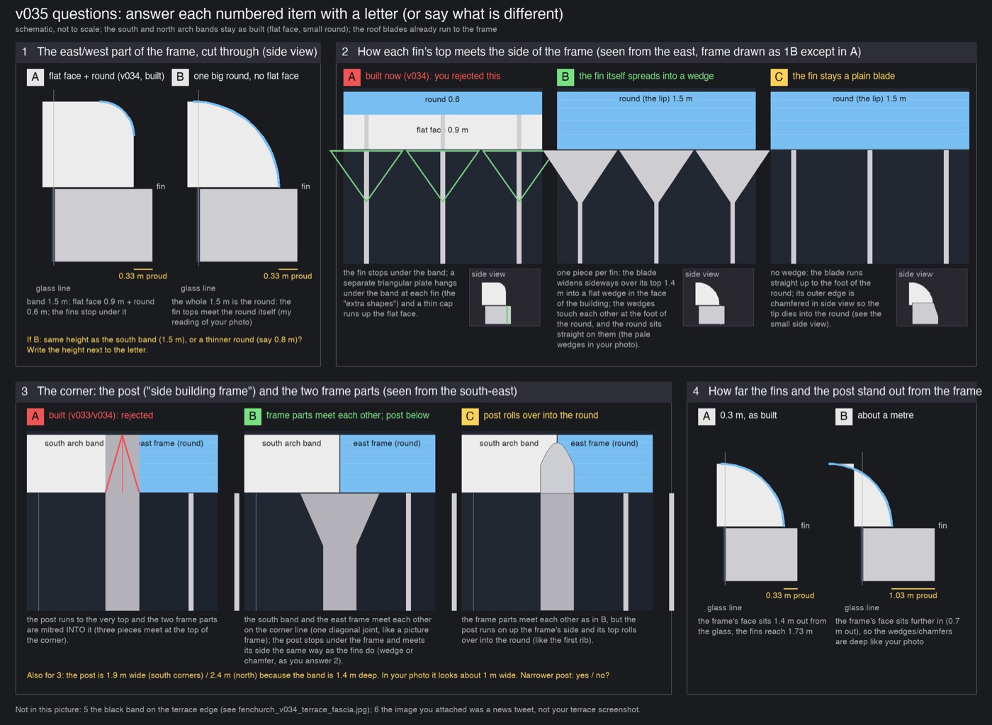
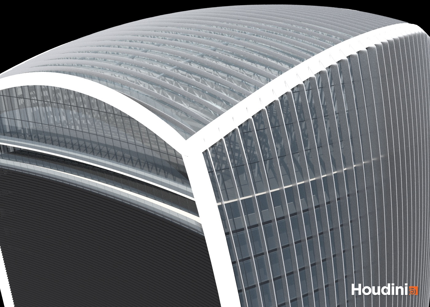
The crown took longer than everything else put together. The roof over the sky garden arches up on the south and north, the side frames have to meet it at the corners, and the fins run up into the frame. Getting those corners to read right took about a dozen versions. Claude kept trying to read the joint off reference photos and kept adding pieces that weren’t there, like caps, gussets and a lip, and at one point it drew me a sheet of lettered options to pick from. What finally worked was describing the corner to it in plain words: the frames meet in a square mitre, the fins and the corner post stop on the top edge of the frame with a 45 degree trim, and the dark bit in the photo is just shadow. It built exactly that, and after one more round of tidying the gaps it was done.
The sky garden and the hero floors
Inside the crown are 25 lattice arches holding up the roof, built as leaning trusses that follow its curve. The floors that will be seen breaking up close (L16 to L36, set in the params) get an interior too: core walls, lift shafts, stairs, raised floors and ceilings, so there’s something behind the glass when it goes. I tried the roof crane up there for a version as well and took it out again, because it looked out of place in the shot.


Sunshades
The south face has a louvre on every bay of every floor, nearly 8,000 of them. The controls node has a tab where you pick a range of floors and an angle, and you can stack as many of those groups as you like. It works on the cached geometry, so it’s quick to play with, and the validation turns every blade to 0 and 90 degrees and checks that none of them hit each other or the glass at any angle.


Handing it over to fracture
The last step packs every piece by name, adds a group for each material and builds a starter constraint network: 198,104 glue constraints between pieces that touch, with a strength for each pair of materials so the glass lets go before the mullions and the mullions before the slabs. I’m building my own fracture tool to go on top of this (shapes to pick the area, then the floors, glass and fins fractured separately), so the generator stops here on purpose and doesn’t touch the sim.
Rendering
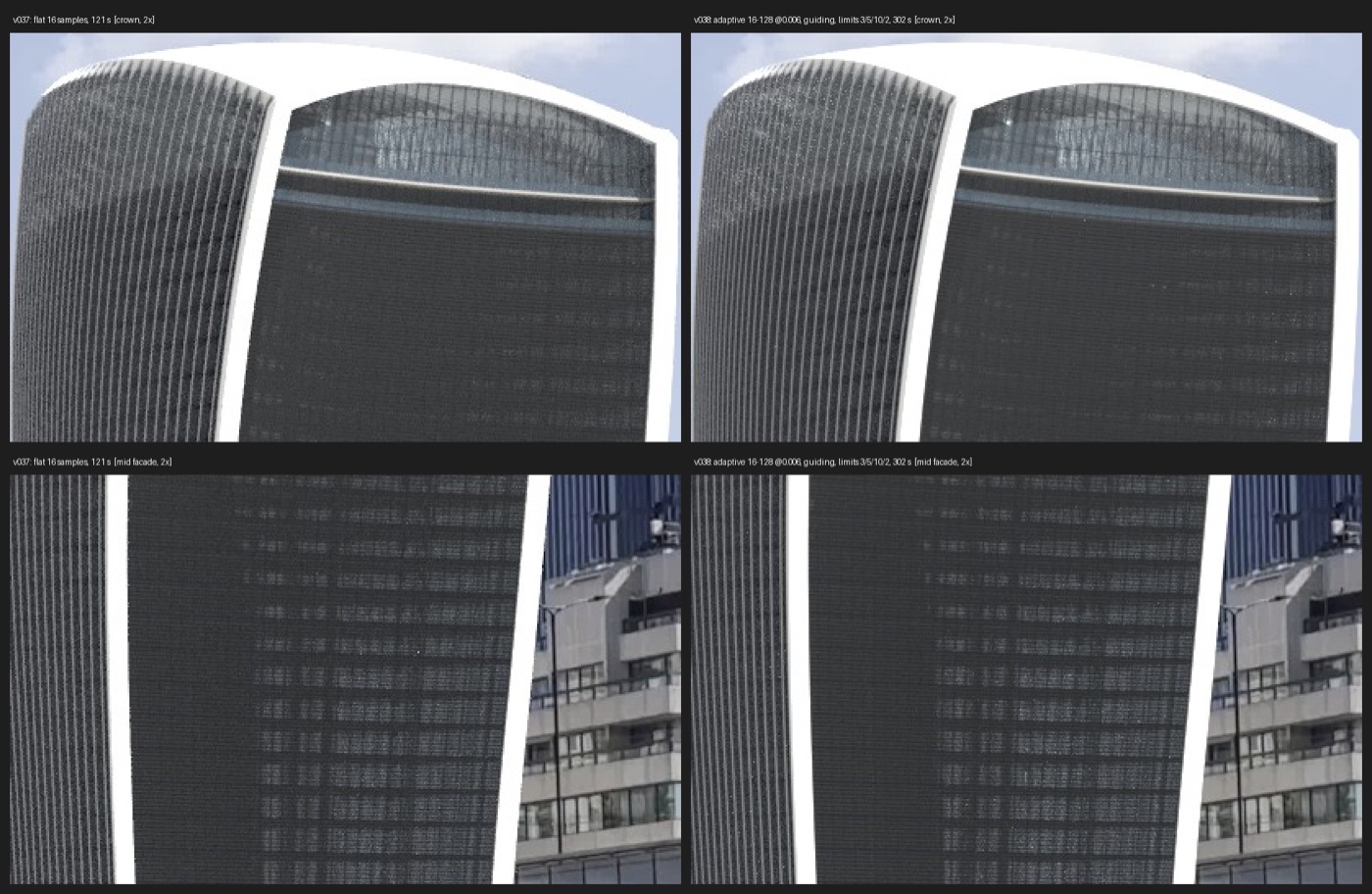
Karma, with render settings I worked out in another chat with Claude: adaptive sampling, path guiding, a proper sun angle, and AOVs and light groups for the comp. Frame 1 takes about five minutes on my laptop, so all 378 frames would be over a day. That’s going on the M2 Ultra. The Houdini logo in the corner of everything is because I’m on Apprentice.
How it’s built
All of the code was written by Claude Code, talking to Houdini through an MCP server. The rule from the start was that the code is the asset: Claude doesn’t edit nodes by hand in the scene, it changes the Python and rebuilds. The generator is about 4,200 lines of Python, plus a few tools for fitting cameras to photos. It went in phases (references, parameters, structure, facade, hero detail and fracture prep) and stopped at the end of each one for me to look. I reviewed every version by eye through the plate camera and sent back screenshots with notes, and every version that passed validation went into Perforce. That’s 38 versions in a week. It’s all Houdini 22 Apprentice on a Mac, with Nuke Non-Commercial for the plate.

No Comments